PID Self‑Balancing Robot Using MPU6050 — College Robotics Project
Self‑balancing robots are one of the most visually exciting and conceptually rich projects in robotics. They combine sensor fusion, control systems, feedback loops, and real‑time embedded programming to keep a robot upright — much like a miniature Segway!
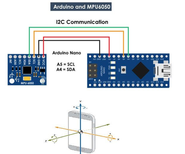 In this project, we use an MPU6050 IMU (Inertial Measurement Unit) and a PID controller to maintain balance dynamically. The robot constantly reads sensor data, calculates the tilt angle, and adjusts wheel motion to stay upright.
Below are two excellent videos that demonstrate the build process and real test results.
🎥 Project Videos
🤖 Full Tutorial & Demonstration
🔄 Short Demo Clip
🧠 What Is a Self‑Balancing Robot?
A self‑balancing robot is essentially an inverted pendulum system. Unlike most robots that work on static balance, this robot uses sensors and feedback control to actively counteract the force of gravity.
At each instant:
- The robot measures its tilt using the MPU6050 IMU (combining accelerometer + gyro).
- A PID control algorithm computes how much correction is needed.
- The motors are commanded to respond, keeping the robot balanced.
It’s a real‑time closed‑loop system that adjusts itself hundreds of times per second — making it a perfect showcase of control theory in action.
🔍 How It Works
🧪 1. Sensor Fusion with MPU6050
The MPU6050 gives:
- Accelerometer readings (tilt + gravity)
- Gyroscope readings (rotational rate)
We combine these using a complementary filter to estimate the robot’s angle accurately:
angle = α * (angle + gyro_rate * dt) + (1 − α) * accel_angle
This smooths out noise and keeps the measurement stable.
⚙️ 2. PID Control
PID (Proportional–Integral–Derivative) is key to stable balancing:
- P (Proportional): reacts to current tilt
- I (Integral): corrects accumulated offset
- D (Derivative): anticipates future movement
The control loop calculates a motor speed correction based on:
error = desired_angle − measured_angle
correction = Kp * error + Ki * integral(error) + Kd * derivative(error)
Tuning these three gains (Kp, Ki, Kd) is the essence of stable balance.
🛠️ Components Used
| Component | Purpose |
|---|---|
| Arduino Uno / Nano | Brain of robot |
| MPU6050 IMU | Tilt & angular rate sensing |
| Motor Driver (L298N / TB6612) | Controls motors |
| DC Motors + Wheels | Movement & balance correction |
| Chassis & Battery | Structure and power |
These parts come together to create an intelligent robot that literally balances itself.
💡 Why This Project Is Worth Doing
This self‑balancing robot project teaches:
- Control systems fundamentals
- Sensor fusion and filtering
- Feedback loops & real‑time decisions
- Embedded programming
- Mechanical & electrical integration
It’s one of those builds that feels magical the first time it works — and deeply educational the second time.