Building an Autonomous Line Follower: A Hands-On Robotics Journey with Arduino
Robotics today is no longer limited to industrial labs or high-end research facilities. Thanks to open-source microcontrollers like Arduino, learning robotics has become accessible, affordable, and irresistibly fun. One of the most iconic beginner-to-intermediate robotics projects is the Line Follower Robot — a small autonomous vehicle that follows a visual path using sensors and feedback control.
🎥 Watch the Line Follower Demo
Below is a helpful video tutorial showing a Line Follower Robot in action — from wiring to programming:
A great example of this in practice is the Arduino Line Follower project by Chris Sunny. The project is neat, compact, and practical — a complete mini-course in sensors, control theory, and embedded programming.
A Code-Driven Robotics Project
At its core, a line follower robot is a smart feedback system:
- Sensors detect the position of the line
- A controller computes error
- The motors respond by correcting direction
This project uses Arduino, the go-to platform for hobbyists and students, because of its simplicity and massive community support. With just a few lines of code, you can turn a handful of components — motors, IR sensors, and a microcontroller — into a fully autonomous robot.
The real magic lies in how software transforms hardware into a thinking machine.
Understanding Line Following: The Error Signal
Every line follower works by measuring how far the robot is from the line. This difference is called error. When the robot drifts left, error becomes negative; when it drifts right, error becomes positive.
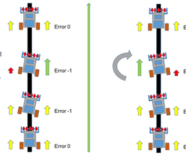
Your job as the programmer is to convert this “error” into motor corrections. The smoother your correction, the more natural your robot’s movement becomes — and that’s where control algorithms come in.
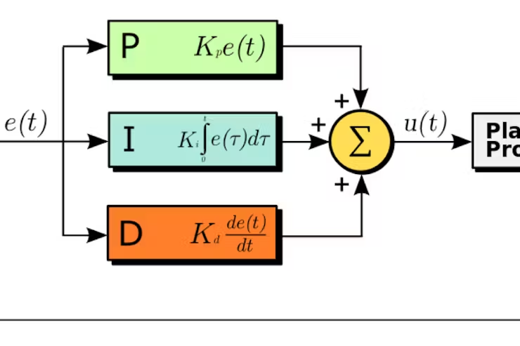
Mastering Control with PID
The heart of this robot is a PID (Proportional–Integral–Derivative) controller — one of the most powerful tools in engineering. PID takes the “error” and produces a perfectly balanced correction output for the motors.
Here is what PID brings to the table:
- P (Proportional): Corrects based on current error
- I (Integral): Fixes accumulated past errors
- D (Derivative): Predicts and smooths future motion
Together, they produce incredibly stable and responsive behavior.
With the right PID tuning, your robot can glide through curves, take sharp bends, and stay on track even at higher speeds.
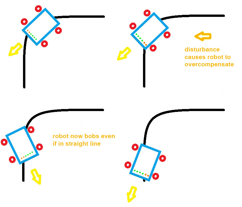
The Art of Sensor Compensation
Real-world robotics is never perfect. Sensors produce noise, lighting changes, and surfaces vary. This is where sensor compensation comes into play — adjusting your readings so the robot can make sense of imperfect data.
In this project, compensation helps correct:
- uneven lighting
- reflective tape variations
- IR sensor drift
- left–right threshold inconsistencies
This transforms a simple IR array into a reliable “vision” system that the Arduino can use to make high-speed decisions.
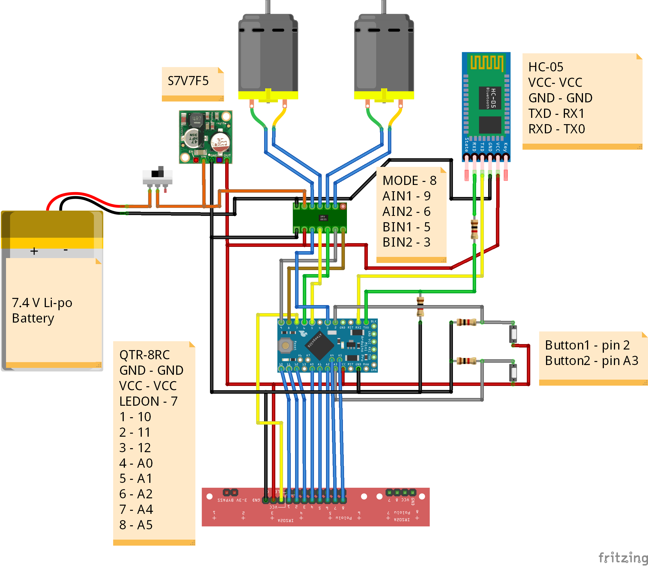
What’s Inside the Project?
A typical Arduino line follower contains the following components:
- IR Sensor Array – Reads the position of the line
- Differential Drive Motors – Provide movement
- Motor Driver (L298N / L293D) – Controls the motors
- Arduino Uno / Nano – Brains of the robot
- PID Algorithm – Ensures smooth path following
- Error Calculation Logic – Finds line deviation
- Compensation Algorithms – Cleans noisy sensor data
This project combines all these elements into a clean, functional robotics pipeline — ideal for learners and hobbyists.